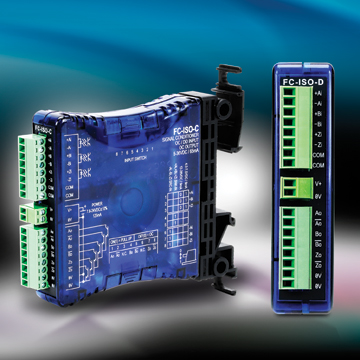

Data lines are designated A, B, Z, A/, B/, Z/ at the module Differential line driver (Use Connection Instructions #1) Single ended line driver (Use Connection Instructions #2) Single ended open collector with pull-up resistors internal to encoder (Use Connection Instructions #3) Single ended, open collector (Use Connection Instructions #3) 5 VDC (TTL, RS422 compatible, line driver) 12-15 VDC 24VDC 1 MHz, maximum 5-28 VDC ±5%, 75mA plus load current 28V/V Line Driver, 100mA source/sink, Vout = Vin 28V/5 Line Driver, 100mA source/sink, Vout = 5V (Derate output current to 50mA with supply voltage > 12VDC) 28V/OC NPN Open Collector, 80mA sink Supply lines protected against over voltage to 60 volts and reverse voltage Available as –S Special Feature Tel: 80/80 | Fax: 80/ 80 | 7230 Hollister Ave, Goleta, CA 93117-2807| Specification No.

OPTICAL ISOLATOR MODULE CODE
22.5 mm (0.89 inches) 114.5 mm (4.51 inches) 99 mm Output Code Format From Encoder Output Signal Type From Encoder Output Signal Voltage Level From Encoder Frequency Response of Optical Isolator Power Requirements For Optical Isolator Optical Isolator Output Options Protection Level Tristate Outputs Dual Channel in quadrature plus index and complements. It has a 1 MHz throughput capability and can be used wherever a fast, optically isolated interface is required. This Optical Isolator can help clean up noisy signals by converting to a different line driver output. Up to eight Optical Isolator Modules can be daisy-chained to provide multiple, simultaneous outputs to controllers or PLC’s. It accommodates all standard operating voltages from 5 to 28 VDC. It accepts single ended or differential inputs and provides single ended or differential outputs in either an open collector or line driver configuration. It effectively isolates medical equipment to protect patients, yet allows data to flow at Gigabit Ethernet speeds. This is a versatile interface between an incremental encoder and receiving electronics. Tripp Lites N234-MI-1005 medical Ethernet isolator protects staff, patients and medical technology equipment in patient care vicinities from dangerous leakage currents that can travel through a copper-based Ethernet network.

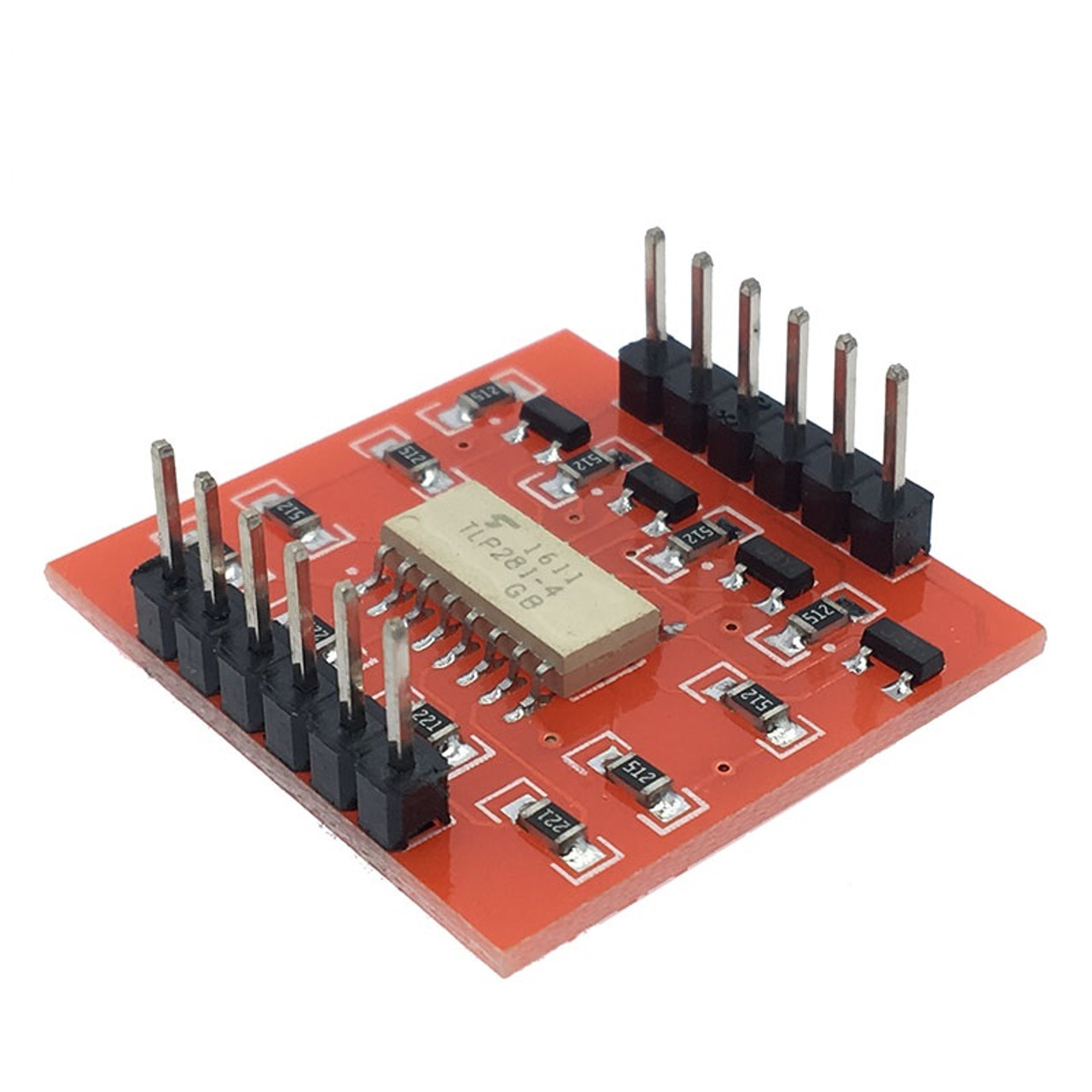
The module simply snaps directly to the DIN rail and is ready to use. A length of DIN rail is supplied with each module. The package mounts to a DIN rail type EN 50 022 (35mm X 7.5mm). You’ll typically find these devices being used for: Microprocessor input/output switching DC and AC power control Communications equipment protection Power supply regulation. MECHANICAL SPECIFICATIONS Package dimensions are 114.4 mm high by 99 mm wide by 22.5 mm thick. Optocoupler isolator can be used with other electronic devices to provide isolation between low and high voltage circuits.
OPTICAL ISOLATOR MODULE FREE
SIGNAL: Specifying an optical isolator module requires knowledge of three system parameters: the DC supply voltage available in the system the encoder output type (logic levels and driver type) and the input signal specifications of the receiving electronics. Terminal Block Vout Vin 28V Maximum Electronic Module BEI Sensors 60001-008 Electronic Module Isolator Circuit Optical Isolator 11-19V Logic EM-DR1-IC-15-TB-28V/V Tax-Free Free Shipping FREE Shipping Over 15 free distribution, US 688. Any encoders used in conjunction with this module must be connected to their own power. The optical isolator module does not provide power to the encoder. changeover switches - auxiliaries and accessories Isolator switches. The module draws approximately 75 mA and a green LED indicates the unit is powered. Add-on modules DX - for 1 module/pole DX MCBs Add-on modules DX - for 1.5. It should never be connected directly to AC power mains. The inputs have a relay driver transistor and opto-isolator built-in which means the device needs 2.OPTICAL ISOLATOR ELECTRONIC MODULE ELECTRICAL SPECIFICATIONS POWER: The optical isolator can accommodate standard operating voltages from 5 to 28 VDC. These relays are fully 5V logic compatible. The main downside to relays is that being an electro-mechanical device, like any mechanical switch relays are more prone to wear and tear over prolonged use. They are also nicely contained little modules that are simple to hook-up and are especially useful for switching AC. Unlike transistors used for switching, relays use metallic switch contacts which avoids the power loss and heating inherent in transistor switching circuits. Relay modules are handy for controlling external loads. Now, two independent groups show that a phonon-mediated break of the chiral symmetry in waveguide. Can operate with opto-isolation or without it Practical on-chip optical isolators providing non-reciprocal propagation are still a challenge.LED indicators when relays are energized.Normally Open (NO) and Normally Closed (NC) contacts Specifying an optical isolator module requires knowledge of three system parameters: the DC supply voltage available in the system the encoder output type (.KEY FEATURES OF RELAY MODULE 5V X 8 RELAY W/ OPTO-ISOLATION: Relay Module 5V x 8 Relay w/ Opto-isolation.The relay module has eight independent 5V logic compatible relays that control or up to each.


 0 kommentar(er)
